The Padua metrobus and the Mestre tram
System engineering for urban transport - two enlightening cases
The Padua Metrobus and the Mestre Tram are two examples of the application of system engineering: a methodology of ‘doing’ which NET Engineering has always pioneered and is now a distinctive element in the Group’s operating style. It is a logical process generated by the qualitative and quantitative observation of the present and future mobility needs of people and goods. It determines the definition of the ‘integrated transport service plan’ and is perfected with recognition of the infrastructure complex for the implementation of the plan. The system analyses and assesses the current situation, forecasts the evolution of the infrastructure network and that of the demand for transport, finds the possible proposals for action, checks their impact on the context, traffic and environment, indicates the optimal design solution and carries out an economic assessment.
The system approach used led to the design of two civil infrastructures in accordance with the needs expressed by the operating model developed on the basis of in-depth transport assessments. This design approach contributed to making the Padua Metrobus (SIR) and the Mestre Tram (STG) real ‘integrated’ transport projects intended to minimise the impact on traffic circulation and maximise the potential for access to the new service through the reasoned transfer of exchange car parks and stops. The approach also implied in-depth analysis of transit points, necessary for achieving the best urban-planning integration, also through perceptive physical simulation techniques.

The Padua Metrobus
Intermediate guided transport system
For Padua, the ‘SIR’ system, also known as ‘Metrobus’, is the new collective public transport system in the city and has three long tramways – north/south, east/west and centre/south-east. Let’s have a look in detail.

NET Engineering was assigned to design the line system for SIR2, covering 14.6 km, with a total of 29 stops, and SIR3, which with 12 stops on a route of about 6 km to serve the Trade Fair and the hospital district. For the infrastructure, the system has a central monorail on a platform wide enough to hold the wheels of a road tram, also known as ‘Metrobus’.
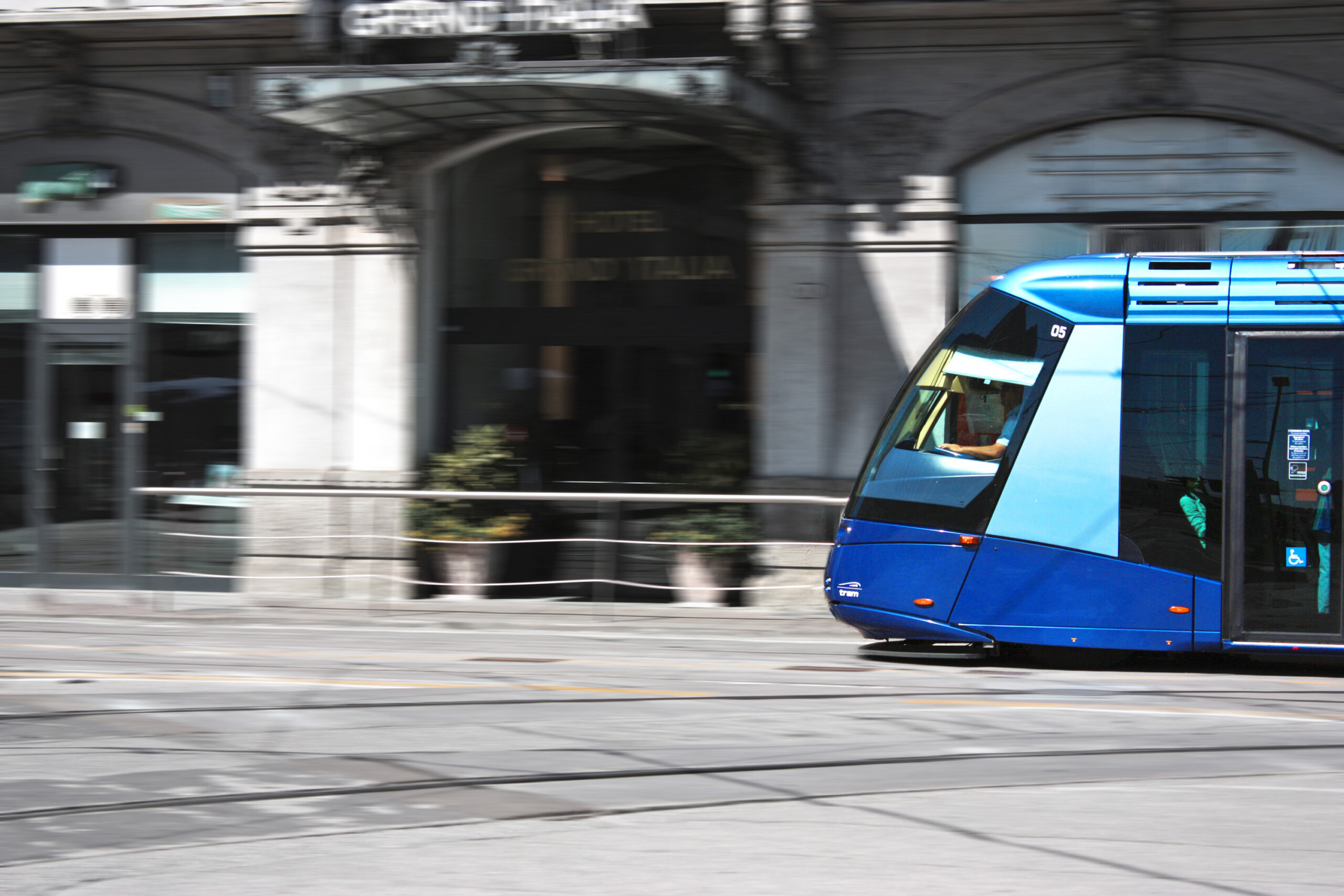
It uses TRANSLOHR STE3 electrically-driven vehicles with 4 carriages, powered by a single wire with a return through the rail, able to communicate with the signaling systems on the ground thus giving further optimization for the travel times.
The definition of the route also took into account the results of the transport studies and was finalised to maximise the use of dedicated lanes (available for almost 90% of the way) so that passengers were guaranteed certain travel times. Various alternatives for the route were analysed in the preliminary project which, considering the route of the SIR2, set out in the Urban Mobility Plan for Padua, as unchanged, focused on finding the best configuration of the different roads, assessing the result from the point of view of the effectiveness of the route, the impact on the other traffic components, the environmental impact and the construction costs. In particular, the placement of the route was assessed with the guideway on the side, central and with both guideways on one side.

Analysed three levels of details:
- Contest:
- Content:
- Effect:


The Mestre Tram
Rubber-tyred guided tram system (STG)
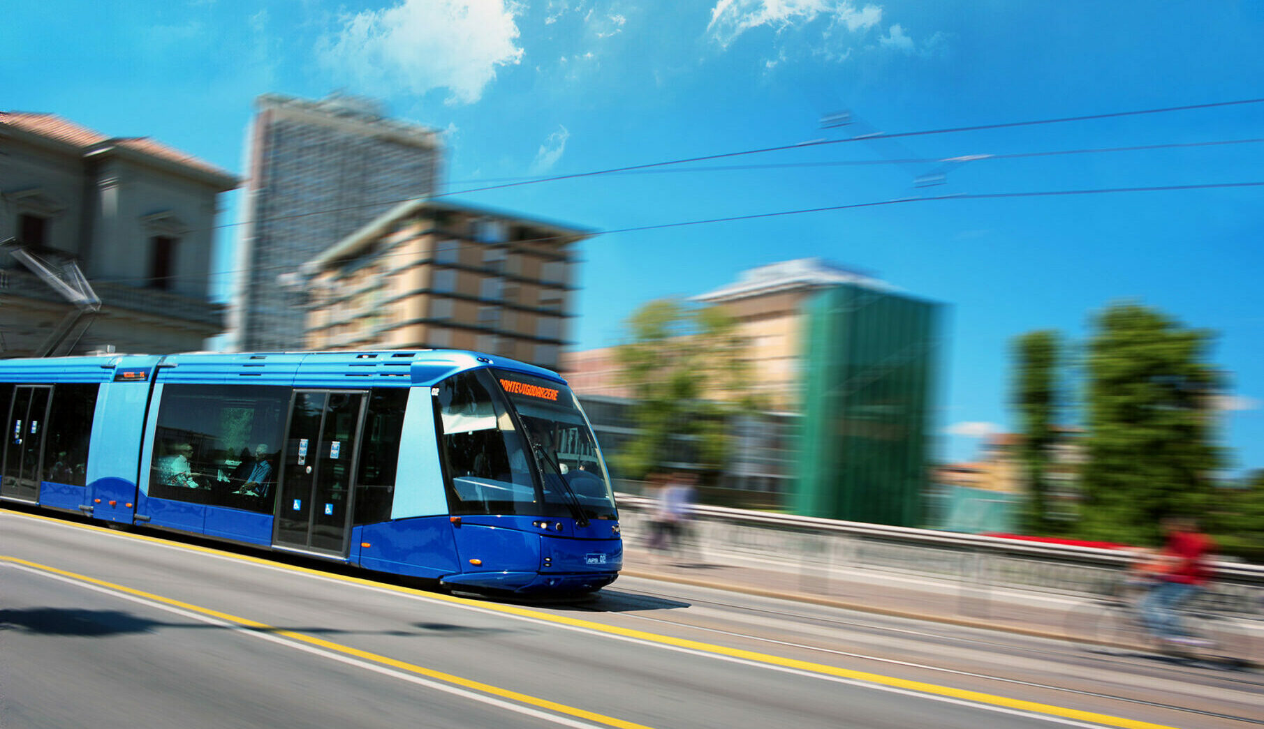
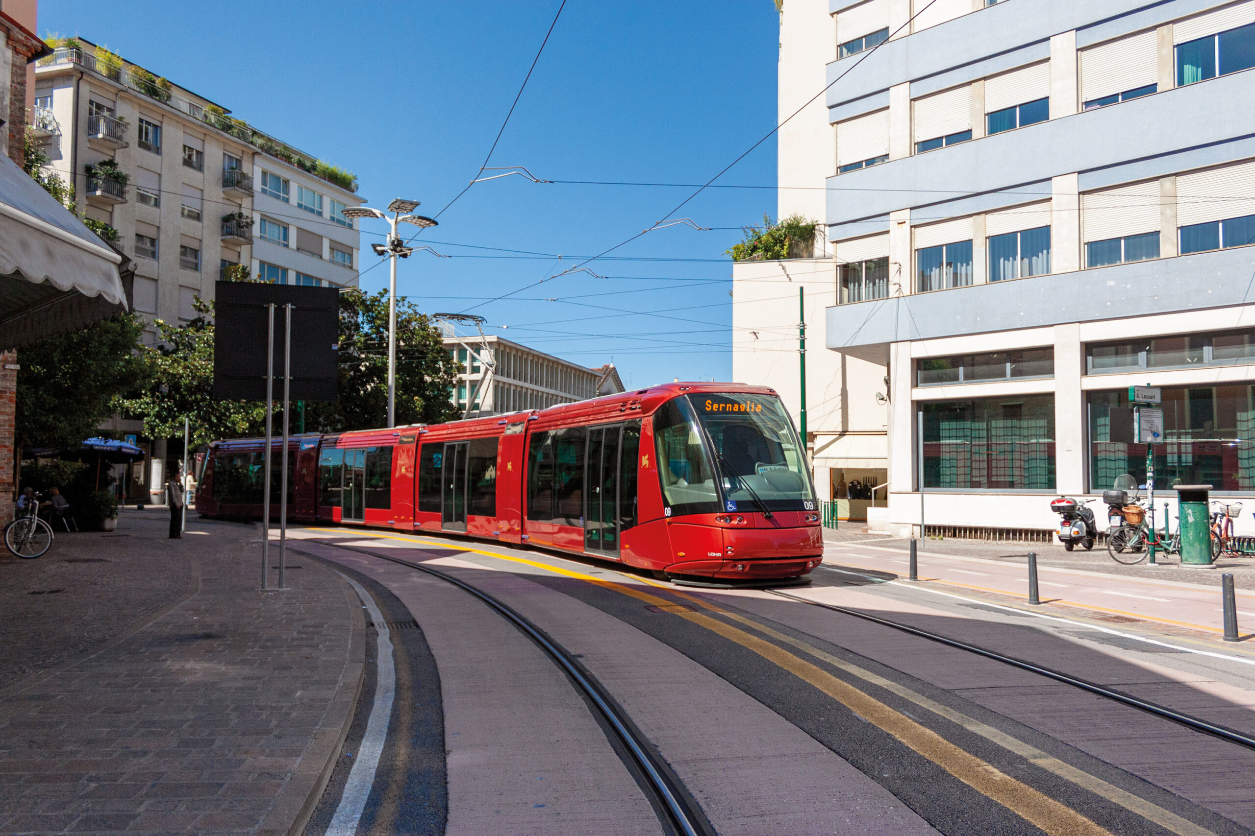
The project concerned the creation of the rubber-tyred guided tram system for Mestre and Venice, divided into two lines. Line 1 starts in Favaro, transits the interchange with Line 2 in Piazzale Cialdini, Mestre, and terminates in Piazzale Roma, Venice, covering a route of about 14 km. Line 2, about 6 km long overall, starts at the interchange, crosses the centre of Mestre, passes under the railway lines at the station and reaches Marghera at the Panorama Terminus. There are 34 stops overall and the system travels a densely urbanised area, requiring the inclusion of the route in the complex network of urban streets. These are some of the reasons why a silent and innovative transport system was chosen. Its silence is due to the use of a rubber-tyred guided tram system (TRANSLOHR) with a central monorail, fixed to a reinforced concrete platform suitably roughened on the surface, wide enough for the tyres to drive on.

In this context, NET Engineering took care of the final and construction design of the platform and interchange in Piazzale Cialdini, Mestre, the construction site set-up and the study of the road signs and roads. It also aided the sub-contracting Temporary Association of Businesses during the infrastructure construction stages.
The design of the platform – segments with an average length of 28 metres – was based on the study of the terrains crossed. The lagoon area, mainly clay, had low bearing capacity and a more salty air which led Net Engineering to be oriented to a rigid type of paving 28 cm thick, made of high durability concrete. The cable ducts, to power the drive, were housed underneath, in a protected position. The reduced thickness of the tramway platform has allowed to keep the position unchanged for most important subservices, mainly the sewer system and electric lines to remain unchanged, ensuring their extraordinary maintenance without interrupting operation through the possibility of making the platform free-standing at certain points of the route.
Other services were moved to facilitate maintenance. The route had to be in a reserved lane to ensure the efficiency of the operation of the new infrastructure, and this could be guaranteed for more than 60% of the route.
The main challenge for the NET Engineering designers related to the section of the route on the Ponte della Libertà in Venice. Different technology was suggested for this with the creation of a hard-wearing, highly resistant kerbstone of modified bitumen requiring low maintenance able to deal with the subsidence due to the continuous passing of the tram.
This solution, much closer to traditional flexible paving, allowed the work to be started and fulfilled, reducing the time required and so limiting the impact on the existing traffic on the bridge.

